Tuesday, December 12, 2017
Thursday, October 6, 2016
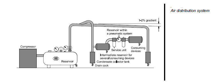
Air generation and distribution
The compressed air supply for a pneumatic system should be adequately calculated and made available in the appropriate quality. Air is compressed by the air compressor and delivered to an air distribution system in the factory. To ensure the quality of the air is acceptable, air service equipment is utilized to prepare the air before being applied to the control system.
Malfunctions can be considerably reduced in the system if the compressed air is correctly prepared. A number of aspects must be considered in the preparation of the service air:
- Quantity of air required to meet the demands of the system
- Type of compressor to be used to produce the quantity required
- Pressure requirements
- Storage required
- Requirements for air cleanliness
- Acceptable humidity levels to reduce corrosion and sticky operation
- Lubrication requirements, if necessary
- Temperature of the air and effects on the system
- Line sizes and valve sizes to meet demand
- Material selection to meet environmental and system requirements
- Drainage points and exhaust outlets in the distribution system
- Layout of the distribution system to meet demand.
As a rule pneumatic components are designed for a maximum operating pressure of 800-1000 kPa (8 - 10 bar) but in practice it is recommended to operate at between 500-600 kPa (5 and 6 bar) for economic use. Due to the pressure losses in the distribution system the compressor should deliver between 650-700 kPa (6.5 and 7) bar to attain these figures. A reservoir should be fitted to reduce pressure fluctuations. In some cases, the term ‘receiver’ is also used to describe a reservoir.
The compressor fills the reservoir which is available as a storage tank.
The pipe diameter of the air distribution system should be selected in such a way that the pressure loss from the pressurised reservoir to the consuming device ideally does not exceed approx. 10 kPa (0.1 bar). The selection of the pipe diameter is governed by:
- Flow rate
- Line length
- Permissible pressure loss
- Operating pressure
- Number of flow control points in the line
- Ring
Wednesday, October 5, 2016
Capacitance - Capacitor Connections
Capacitance adds when capacitors are connected in parallel. It diminishes when capacitors are connected in series:

Recall that capacitance stores energy in the form of an electric field, as a function of the voltage applied to it. It we wish to increase capacitance by connecting multiple capacitors to each other, we need to do that in such a way that each capacitor receives the same (total) applied voltage so that each additional amount of capacitance included in the network will contribute a proportional amount of energy storage to the network. We know voltage is guaranteed to be equal only among parallelconnected components. If we were to connect multiple capacitors in series with one another, their individual voltages would be some fraction of the total voltage (series voltages always adding to equal the total voltage), thus diminishing the energy stored in each capacitor and similarly
diminishing the total capacitance. Another way to comprehend why capacitance increases in parallel and diminishes in series is to consider a network of capacitors as one equivalent capacitor in terms of aggregate plate area and separation distance. Examining the directions of change to the corresponding variables in the permittivity/area/distance formula for capacitance, we see how parallel-connected capacitances must add while series-connected capacitances must diminish:

Monday, October 3, 2016
Capacitors
Any two electrical conductors separated by an insulating medium possess the characteristic called capacitance: the ability to store energy in the form of an electric field created by a voltage between those two conductors. Capacitance is symbolized by the capital letter C and is measured in the unit of the Farad (F). The relationship between capacitance, stored electric charge (Q), and voltage (V) is as follows:
Q = CV
For example, a capacitance having a value of 33 microfarads charged to a voltage of 5 volts would store an electric charge of 165 microcoulombs. Capacitors are devices expressly designed and manufactured to possess capacitance. They are constructed of a “sandwich” of conductive plates separated by an insulating dielectric. Capacitors have maximum voltage ratings as well as capacitance ratings. Here are some schematic symbols for capacitors:

Sunday, October 2, 2016
Structure and signal flow of pneumatic systems
Pneumatic systems consist of an interconnection of different groups of elements.

This group of elements forms a control path for signal flow, starting from the signal section (input) through to the actuating section (output). Control elements control the actuating elements in accordance with the signals received from the processing elements.
The primary levels in a pneumatic system are:
- Energy supply
- Input elements (sensors)
- Processing elements (processors)
- Control elements
- Power components (actuators)
Thursday, September 29, 2016
Pneumatics Basics - (Festo Ref.)
Pneumatics has for some considerable time been used for carrying out the simplest mechanical tasks, but in more recent times has played a more important role in the development of pneumatic technology for automation.
In the majority of applications compressed air is used for one or more of the following functions:
- To determine the status of processors (sensors)
- Information processing (processors)
- Switching of actuators by means of final control elements
- Carrying out work (actuators)
To be able to control machinery and installations necessitates the construction of a generally complex logic interconnection of statuses and switching conditions. This occurs as a result of the interaction of sensors, processors, control elements and actuators in pneumatic or partly pneumatic systems.
Wednesday, September 28, 2016
Electromagnetism
The fundamental principle of electromagnetism is that an electric current will create a magnetic field at right angles to the direction of the current. If the electric current travels in a straight path, the lines of magnetic flux will form concentric circles around that path. If the electric current travels in a circular path (i.e. through a loop or coil of wire), the magnetic lines of flux will form straight lines down the center of the coil, wrapping around at the ends to form a complete loop of its own:

Magnetic field strength is directly proportional to the amount of current in the conductor (and also directly proportional to the number of “turns” in a coiled wire), such that the unit of measurement for magnetic field strength is the amp-turn.
Subscribe to:
Posts (Atom)