Showing posts with label Electrical Basics. Show all posts

Wednesday, October 5, 2016

Capacitance - Capacitor Connections

Capacitance adds when capacitors are connected in parallel. It diminishes when capacitors are connected in series:


Recall that capacitance stores energy in the form of an electric field, as a function of the voltage applied to it. It we wish to increase capacitance by connecting multiple capacitors to each other, we need to do that in such a way that each capacitor receives the same (total) applied voltage so that each additional amount of capacitance included in the network will contribute a proportional amount of energy storage to the network. We know voltage is guaranteed to be equal only among parallelconnected components. If we were to connect multiple capacitors in series with one another, their individual voltages would be some fraction of the total voltage (series voltages always adding to equal the total voltage), thus diminishing the energy stored in each capacitor and similarly
 diminishing the total capacitance. Another way to comprehend why capacitance increases in parallel and diminishes in series is to consider a network of capacitors as one equivalent capacitor in terms of aggregate plate area and separation distance. Examining the directions of change to the corresponding variables in the permittivity/area/distance formula for capacitance, we see how parallel-connected capacitances must add while series-connected capacitances must diminish:


Monday, October 3, 2016

Capacitors

Any two electrical conductors separated by an insulating medium possess the characteristic called capacitance: the ability to store energy in the form of an electric field created by a voltage between those two conductors. Capacitance is symbolized by the capital letter C and is measured in the unit of the Farad (F). The relationship between capacitance, stored electric charge (Q), and voltage (V) is as follows:
Q = CV

For example, a capacitance having a value of 33 microfarads charged to a voltage of 5 volts would store an electric charge of 165 microcoulombs. Capacitors are devices expressly designed and manufactured to possess capacitance. They are constructed of a “sandwich” of conductive plates separated by an insulating dielectric. Capacitors have maximum voltage ratings as well as capacitance ratings. Here are some schematic symbols for capacitors:


Wednesday, September 28, 2016

Electromagnetism

The fundamental principle of electromagnetism is that an electric current will create a magnetic field at right angles to the direction of the current. If the electric current travels in a straight path, the lines of magnetic flux will form concentric circles around that path. If the electric current travels in a circular path (i.e. through a loop or coil of wire), the magnetic lines of flux will form straight lines down the center of the coil, wrapping around at the ends to form a complete loop of its own:

Magnetic field strength is directly proportional to the amount of current in the conductor (and also directly proportional to the number of “turns” in a coiled wire), such that the unit of measurement for magnetic field strength is the amp-turn.

Tuesday, September 27, 2016

Null-balance voltage measurement

A number of different sensors used in instrumentation generate DC voltage signals proportional to the process variable of interest. We call such sensors potentiometric, which literally means “voltagemeasuring”. Thermocouples are one type of potentiometric sensor, used to measure temperature.
Photodiodes are another, used to measure light intensity. Glass pH electrodes are yet another, used to measure the hydrogen ion activity in a liquid solution. It should be obvious that accurate voltage measurement is critical for any instrument based on a potentiometric sensor, for if our measurement of that sensor’s output voltage is not accurate, we will surely suffer inaccurate measurement of any process variable proportional to that voltage (e.g. temperature, light, pH).  One common obstacle to accurate sensor voltage measurement is the internal resistance of the sensor itself. We will explore this concept by way of a practical example: trying to measure the voltage output by a pH electrode pair using a standard digital voltmeter. A pictorial diagram shows the basic concept, where a voltmeter is connected to a pH electrode pair immersed in a liquid solution:


Monday, September 26, 2016

Bridge circuits - Applications Part 2 (Sensor signal conditioning)

A different application for bridge circuits is to convert the output of an electrical sensor into a voltage signal representing some physical measurement. This is by far the most popular use of bridge measurement circuits in industry, and here we see the same circuit used in an entirely different manner from that of the balanced Wheatstone bridge circuit.


Here, the bridge will be balanced only when Rsensor is at one particular resistance value. Unlike the Wheatstone bridge, which serves to measure a component’s value when the circuit is balanced, this bridge circuit will probably spend most of its life in an unbalanced condition. The output voltage changes as a function of sensor resistance, which makes that voltage a reflection of the sensor’s physical condition. In the above circuit, we see that the output voltage increases (positive on the top wire, negative on the bottom wire) as the resistance of Rsensor increases.

Bridge circuits - Applications Part 1

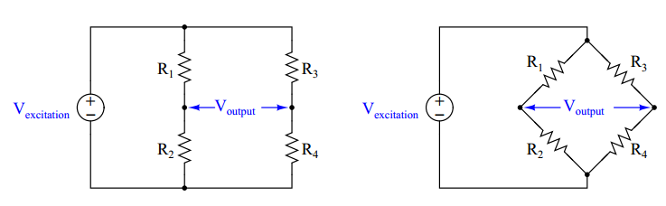
A bridge circuit is basically a pair of voltage dividers where the circuit output is taken as the difference in potential between the two dividers. Bridge circuits may be drawn in schematic form in an H-shape or in a diamond shape, although the diamond configuration is more common:


Sunday, September 25, 2016

Circuit fault analysis

Perhaps the most valuable skill an instrument technician can possess is the ability to efficiently diagnose malfunctioning systems: determining in as short a time as possible the cause of a system’s malfunction. Since most instrumentation and control systems are based on electricity, a solid understanding of electrical faults is the foundation of this skill set. In this section we will explore the two basic types of electrical faults (opens and shorts) and analyze their respective effects in DC circuits.

An open is an electrical fault whereby the pathway for electrical current is broken, thus preventing the passage of current. A short is an electrical fault whereby two points in a circuit that are supposed to be separated are joined together by a conductive pathway. It should be noted that this definition for the word “short” both is technical and specific. This is important to understand, as many people tend to use the word “short” to refer to any electrical problem in general. In technical parlance, a “short” fault is the exact opposite of an “open” fault, and should never be confused one for the other.


Let us examine the effects of both faults in a simple two-resistor DC circuit. We will begin with an analysis of the circuit in a healthy condition, showing all values of voltage and current:


Electrical sources and loads

By definition, and source is a device that inputs energy into a system, while a load is a device that extracts energy from a system. Examples of typical electrical sources include generators, photovoltaic cells, thermopiles, and primary-cell batteries. Examples of typical electrical loads include resistors, lamps, and electric motors.

In a working circuit, electrical sources and loads may be easily distinguished by comparison of their current directions and voltage drop polarities. An electrical source always manifests a voltage polarity in a direction aiding the direction of charge flow. An electrical source always manifests a voltage polarity in a direction opposing the direction of charge flow.

The way in which we designate the direction of current (charge flow) becomes very important here. Since there are two commonly accepted notations – electron flow and “conventional” flow, exactly opposite of each other – it is easy to become confused.

First we see a diagram showing a source and a load, using electron flow notation. Electrons, being negatively charged particles, are repelled by the negative ( ) poles of both source and load, and attracted to the positive (+) poles of both source and load. The difference between source and load is that the source device motivates the flow of electrons while the load device resists the flow of electrons:


Friday, September 23, 2016

Kirchhoff’s Laws

Two extremely important principles in electric circuits were codified by Gustav Robert Kirchhoff in the year 1847, known as Kirchhoff’s Laws. His two laws refer to voltages and currents in electric circuits, respectively.

Kirchhoff’s Voltage Law states that the algebraic sum of all voltages in a closed loop is equal to zero. Another way to state this law is to say that for every rise in potential there must be an equal fall, if we begin at any point in a circuit and travel in a loop back to that same starting point. An analogy for visualizing Kirchhoff’s Voltage Law is hiking up a mountain. Suppose we start at the base of a mountain and hike to an altitude of 5000 feet to set up camp for an overnight stay. Then, the next day we set off from camp and hike farther up another 3500 feet. Deciding we’ve climbed high enough for two days, we set up camp again and stay the night. The next day we hike down 6200 feet to a third location and camp once gain. On the fourth day we hike back to our original starting point at the base of the mountain. We can summarize our hiking adventure as a series of rises and falls like this:


Series versus parallel circuits

In addition to Ohm’s Law, we have a set of rules describing how voltages, currents, and resistances
relate in circuits comprised of multiple resistors. These rules fall neatly into two categories: series
circuits and parallel circuits. The two circuit types are shown here, with squares representing any
type of two-terminal electrical component:


The defining characteristic of a series electrical circuit is it provides just one path for current.
This means there can be only one value for current anywhere in the circuit, the exact same current
for all components at any given time6. The principle of current being the same everywhere in a
series circuit is actually an expression of a more fundamental law of physics: the Conservation of
Charge, which states that electric charge cannot be created or destroyed. In order for current to
have different values at different points in a series circuit indefinitely, electric charge would have to
somehow appear and disappear to account for greater rates of charge flow in some areas than in
others. It would be the equivalent of having different rates of water flow at different locations along
one length of pipe.

Wednesday, September 21, 2016

Electronic Proximity Examples (NPN - PNP)


For example, here are two schematic diagrams showing two different kinds of electronic proximity switch. The first switch sinks current in from the LED through its output terminal, through its transistor, and down to ground. The second switch sources current from the positive supply terminal through its transistor and out to the LED through its output terminal (note the direction of the thick arrow near the output screw terminal in each circuit :


Electron versus conventional flow

When Benjamin Franklin proposed his single-fluid theory of electricity, he defined “positive” and “negative” as the surplus and deficiency of electric charge, respectively. These labels were largely arbitrary, as Mr. Franklin had no means of identifying the actual nature of electric charge carriers with the primitive test equipment and laboratory techniques of his day. As (bad) luck would have it, his hypothesis was precisely opposite of the truth for metallic conductors, where electrons are the dominant charge carrier. This means that in an electric circuit consisting of a battery and a light bulb, electrons slowly move from the negative side of the battery, through the metal wires, through the light bulb, and on to the positive side of the battery as such:


Monday, September 19, 2016

Electrical current

Current is the name we give to the motion of electric charges from a point of high potential to a point of low potential. All we need to form an electric current is a source of potential (voltage) and some electric charges that are free to move between the poles of that potential. For instance, if we connected a battery to two metal plates, we would create an electric field between those plates, analogous to a gravitational field except it only acts on electrically charged objects, while gravity acts on anything with mass. A free charge placed between those plates would “fall” toward one of the plates just as a mass would fall toward a larger mass:


Electrical Voltage - Part 2 (Electric potential "voltage" and potential energy)

Electric potential (voltage) and potential energy share a common, yet confusing property: both quantities are fundamentally relative between two physical locations. There is really no such thing as specifying a quantity of potential energy at a single location. The amount of potential energy in any system is always relative between two different points. If I lift a mass off the ground, I can specify its potential energy, but only in relation to its former position on the ground. The amount of energy that mass is potentially capable of releasing by free-fall depends on how far it could possibly fall. To illustrate, we will perform some “thought experiments” where we lift a 1 kilogram mass 1 meter off the ground and then drop that mass to assess its energy. That 1-kilo mass weighs 9.81 Newtons on Earth, and the distance lifted was 1 meter, so the potential energy stored in the mass is 9.81 joules, right? Consider the following scenario:


Electrical voltage - Part 1

Voltage is the amount of specific potential energy available between two points in an electric circuit.

Potential energy is energy that is potentially available to do work. Looking at this from a classical physics perspective, potential energy is what we accumulate when we lift a weight above ground level, or when we compress a spring: