A bridge circuit is basically a pair of voltage dividers where the circuit output is taken as the difference in potential between the two dividers. Bridge circuits may be drawn in schematic form in an H-shape or in a diamond shape, although the diamond configuration is more common:
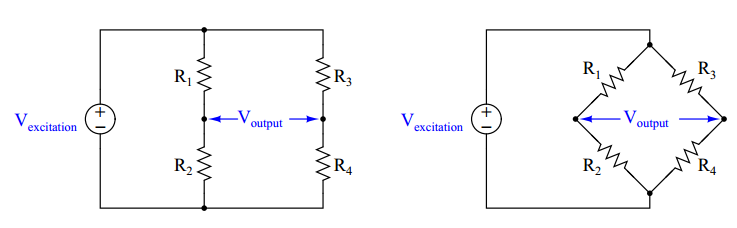
The voltage source powering the bridge circuit is called the excitation source. This source may be DC or AC depending on the application of the bridge circuit. The components comprising the bridge need not be resistors, either: capacitors, inductors, lengths of wire, sensing elements, and other component forms are possible, depending on the application. Two major applications exist for bridge circuits, which will be explained in the following subsections.
Component measurement
Bridge circuits may be used to test components. In this capacity, one of the “arms” of the bridge circuit is comprised of the component under test, while at least one of the other “arms” is made adjustable. The common Wheatstone bridge circuit for resistance measurement is shown here:
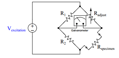
Fixed resistors R1 and R2 are of precisely known value and high precision. Variable resistor R adjust has a labeled knob allowing for a person to adjust and read its value to a high degree of precision. When the ratio of the variable resistance to the specimen resistance equals the ratio of the two fixed resistors, the sensitive galvanometer will register exactly zero volts regardless of the excitation source’s value. This is called a balanced condition for the bridge circuit:
R1 / R2 = Radjust / Rspecimen
When the two resistance ratios are equal, the voltage drops across the respective resistances will also be equal. Kirchhoff’s Voltage Law declares that the voltage differential between two equal and opposite voltage drops must be zero, accounting for the meter’s indication of balance.
It would not be inappropriate to relate this to the operation of a laboratory balance-beam scale, comparing a specimen of unknown mass against a set of known masses. In either case, the instrument is merely comparing an unknown quantity against an (adjustable) known quantity, indicating a condition of equality between the two:

Many legacy instruments were designed around the concept of a self-balancing bridge circuit, where an electric servo motor drove a potentiometer to achieve a balanced condition against the voltage produced by some process sensor. Analog electronic paper chart recorders often used this principle.
Almost all pneumatic process instruments use this principle to translate the force of a sensing element into a variable air pressure.
Modern bridge circuits are mostly used in laboratories for extremely precise component measurements. Very rarely will you encounter a Wheatstone bridge circuit used in the process industries.
No comments:
Post a Comment