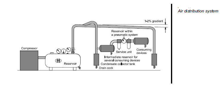
The compressed air supply for a pneumatic system should be adequately calculated and made available in the appropriate quality. Air is compressed by the air compressor and delivered to an air distribution system in the factory. To ensure the quality of the air is acceptable, air service equipment is utilized to prepare the air before being applied to the control system.
Malfunctions can be considerably reduced in the system if the compressed air is correctly prepared. A number of aspects must be considered in the preparation of the service air:
- Quantity of air required to meet the demands of the system
- Type of compressor to be used to produce the quantity required
- Pressure requirements
- Storage required
- Requirements for air cleanliness
- Acceptable humidity levels to reduce corrosion and sticky operation
- Lubrication requirements, if necessary
- Temperature of the air and effects on the system
- Line sizes and valve sizes to meet demand
- Material selection to meet environmental and system requirements
- Drainage points and exhaust outlets in the distribution system
- Layout of the distribution system to meet demand.
As a rule pneumatic components are designed for a maximum operating pressure of 800-1000 kPa (8 - 10 bar) but in practice it is recommended to operate at between 500-600 kPa (5 and 6 bar) for economic use. Due to the pressure losses in the distribution system the compressor should deliver between 650-700 kPa (6.5 and 7) bar to attain these figures. A reservoir should be fitted to reduce pressure fluctuations. In some cases, the term ‘receiver’ is also used to describe a reservoir.
The compressor fills the reservoir which is available as a storage tank.
The pipe diameter of the air distribution system should be selected in such a way that the pressure loss from the pressurised reservoir to the consuming device ideally does not exceed approx. 10 kPa (0.1 bar). The selection of the pipe diameter is governed by:
- Flow rate
- Line length
- Permissible pressure loss
- Operating pressure
- Number of flow control points in the line
- Ring